Electronic_SEU M
The SEU-M project was created to use the numerous Austrian AGTs (Ö-AGT) that are still available as a simple and inexpensive interface to TW39-teletypes. The name 'SEU' (German: Sende-Empfangs-Umsetzer) is based on the SEU-B-cards, which is built into the modern electronic teletype (ED1000). The 'M' stands for MicroController.
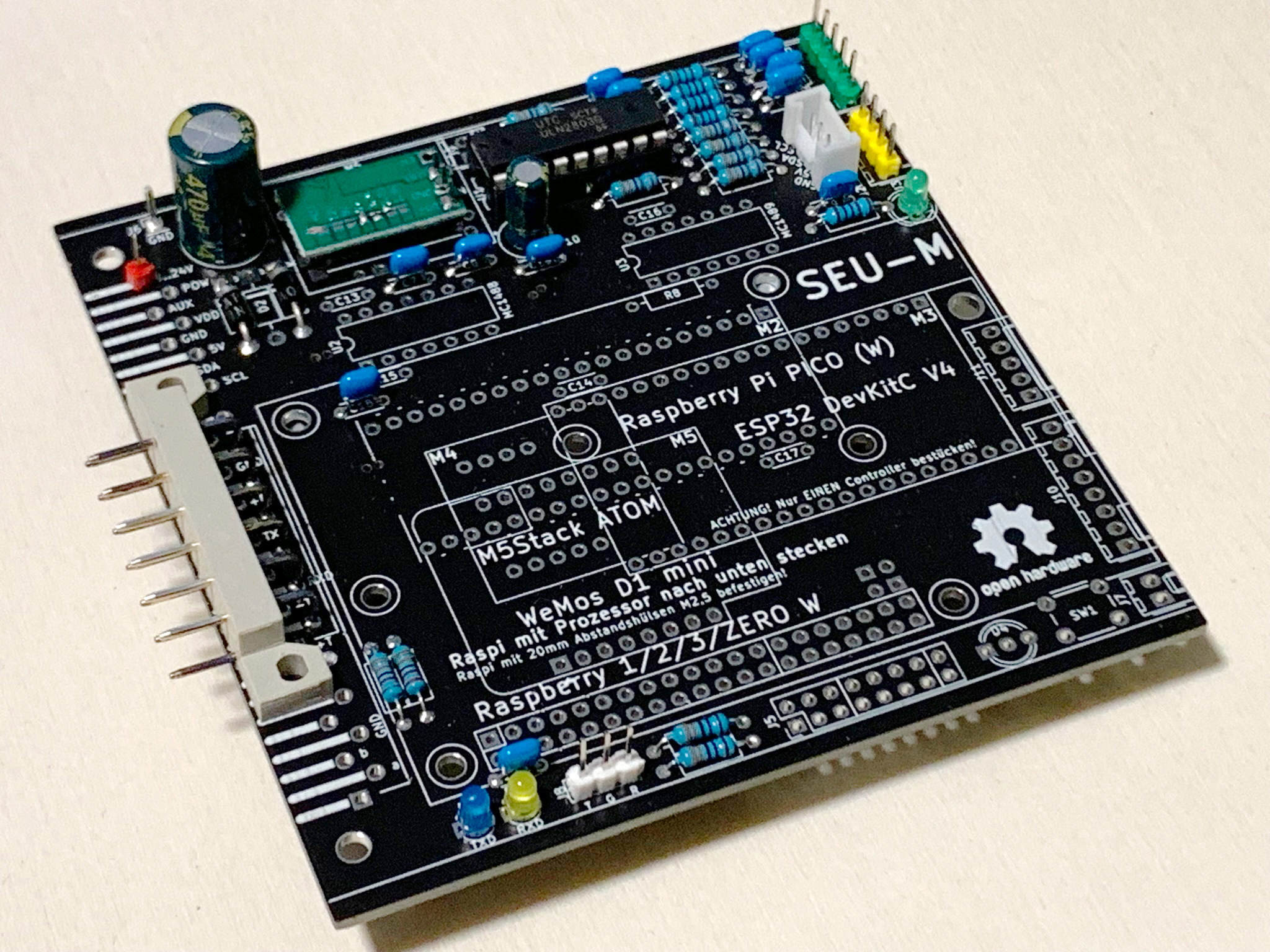
SEU-M is a circuit board that can simply be plugged into an Ö-AGT - and you already have a complete interface between your teletype and the i-Telex network. The card can also replace an SEU-B card in an ED1000-teletype (Lorenz LO2000, LO2001, LO3000) and fulfill all station (VSt) tasks. The board is intended to accommodate various microcontrollers up to the Raspberry Pi.
Software and hardware for this project are open source and open hardware (see links at end of page).

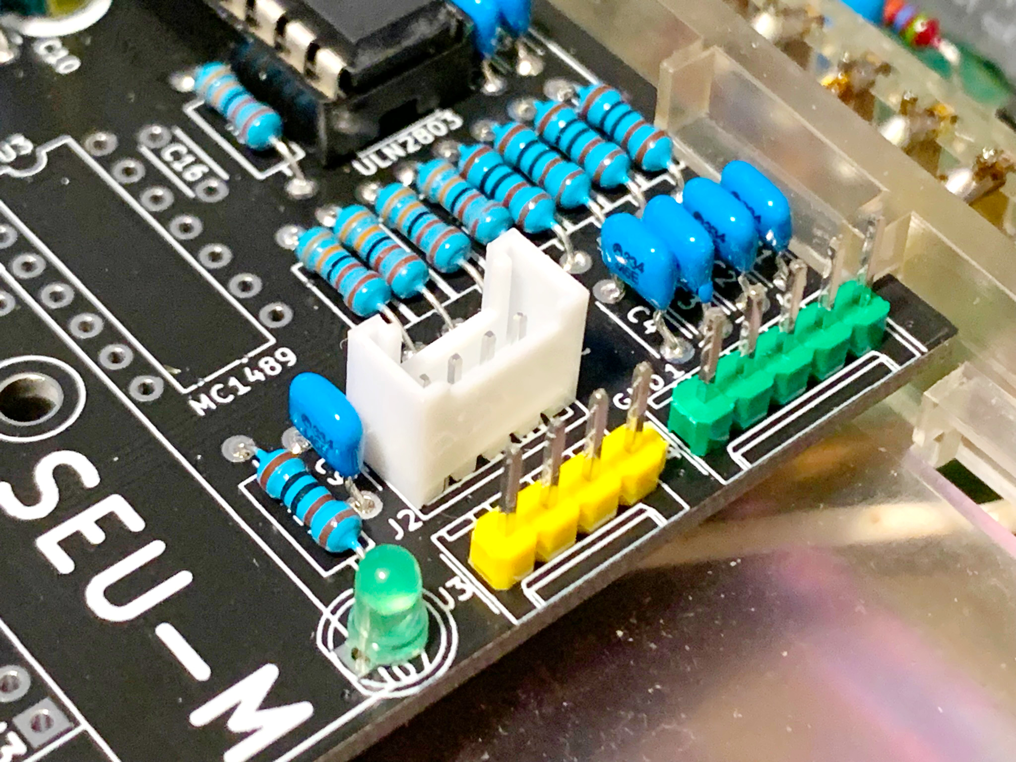
There are two alternative configurations and some options on the card. Depending on the place of use, 2 alternative level converters are provided:
- ULN2003 or ULN2803 with 0…12V level for Ö-AGT
- MC1488 and MC1489 with RS232 level (+/-12V) for LO2000, LO2001, LO3000, T1000S
- Raspberry Pi (1, 2, 3, Zero (W))
- ESP32 DevKitC V4
- Raspberry Pico (W)
- M5Stack ATOM
- WeMos D1 mini (pro)
- (Other Controllers or CH340 interface)
- 4 user button with longer cables (max. 2m)
- 1 user button with short cable (max. 0.2m) - only RPi
- I2C (e.g. display)
- Power relay/SSR
- Aux relay/SSR
- LEDs for 5V, TXD and RXD
- Connector for NeoPixel (WS2812) - only RPi
- Connector for special things (13 GPIOs) - only RPi
- Ö-AGT+T68d: successfully tested with RPi Zero W, RPi 1B, RPi 2B [JK]
- Ö-AGT+FSG+LO15: successfully tested with RPi Zero W [JK]
- Ö-AGT+T37: successfully tested with RPi 1B [WolfHenk]
- LO2000: successfully tested with RPi Zero W, RPi 1B @ 100 Baud [JK]
- LO2001ESR: successfully tested with RPi 1B @ 50 Baud [Simon]
- LO3000: not tested yet, Dimensions checked – RPi 1, 2, 3
- T1000S: not tested yet
The card contains a DC/DC converter to generate the operating voltage for the microcontroller (5V) from 7...24V. Both Ö-AGT and LO2000 provide a voltage of 12V (or up to 24V).
The board layout is designed to hold (mostly) any DC/DC-converter-board available by internet sellers.
Slots for the most common microcontrollers (in the handicraft area) are provided on the SEU-M card. There are a few Telex software projects for ESP8266, ESP32 and RPiPico. These can (or should) be easily converted to the pin assignment of the SEU-M card without any major effort. The SEU-M card is therefore a good platform for experimenting with a microcontroller and a TW39-teletype
Note: All provided controllers (except RPi) are available on the market at fair prices.


All Raspberry Pis (RPi) can be plugged in. In many hobbyist drawers there is still an RPi 1B that can no longer be used for anything else. This is still very well suited for use on the SEU-M card. The current version of piTelex (GitHub, experimental branch) can also be installed on the RPi. The sample configurations (telex.json) for Ö-AGT and LO2000 are available.
Note: At the moment all RPis are not available or are available at overpriced prices. The manufacturer has promised that all RPis will be available to buy in any quantity and at normal prices from mid-2023.
| Pin | Signal | Name | Comment |
|---|---|---|---|
| 2, 4 | +5V | 5V | |
| 1, 17 | +3.3V | 3V3 | |
| 6, 9, 14, 20, 25, 30, 34, 39 | GND | GND | |
| 11 | TXD | GPIO17 | Send data |
| 13 | RXD | GPIO27 | Receive data |
| 15 | POL | GPIO22 | Polarity change |
| 21 | POW | GPIO9 | Power saving relay/SSR |
| 23 | AUX | GPI11 | Aux relay/SSR |
| 19 | DIAL_SW | GPIO10 | Dial switch - connected to RXD over soldering bridge |
| 16 | LED_R | GPIO23 | Duo-LED status, red |
| 18 | LED_G | GPIO24 | Duo-LED status, green |
| 24 | BT1 | GPIO8 | Button 1 |
| 26 | BT1 | GPIO7 | Button 1 |
| 29 | BT1 | GPIO5 | Button 1 |
| 31 | BT1 | GPIO6 | Button 1 |
| 5 | I2C_SCL | GPIO3 | |
| 3 | I2C_SDA | GPIO2 | |
| 8 | Debug TXD | GPIO14 | Linux console |
| 10 | Debug TXD | GPIO15 | Linux console |
| 40 | OFF | GPIO21 | Off button |
| 7 | X1 | GPIO4 | Additional IO |
| 22 | X2 | GPIO25 | Additional IO |
| 32 | X3 | GPIO12 | Additional IO |
| 33 | X4 | GPIO13 | Additional IO |
| 35 | X5 | GPIO19 | Additional IO |
| 36 | X6 | GPIO16 | Additional IO |
| 38 | X7 | GPIO20 | Additional IO |
| 37 | X8 | GPIO26 | Additional IO |

https://www.elektronik-kompendium.de/sites/raspberry-pi/2611051.htm

| Pin | Signal | Name | Comment |
|---|---|---|---|
| 39 | +5V | VSYS | |
| 36 | +3.3V | 3V3 | |
| 3, 8, 13, 18, 23, 28, 33, 38 | GND | GND | |
| 26 | TXD | GPIO20 | Send data |
| 27 | RXD | GPIO21 | Receive data |
| 29 | POL | GPIO22 | Polarity change |
| 21 | POW | GPIO16 | Power saving relay/SSR |
| 22 | AUX | GPIO17 | Aux relay/SSR |
| 4 | BT1 | GPIO2 | Button 1 |
| 5 | BT2 | GPIO3 | Button 2 |
| 6 | BT3 | GPIO4 | Button 3 |
| 7 | BT4 | GPIO5 | Button 4 |
| 25 | I2C_SCL | GPIO19 | |
| 24 | I2C_SDA | GPIO18 |

https://randomnerdtutorials.com/esp32-pinout-reference-gpios/
https://www.mischianti.org/2021/07/17/esp32-devkitc-v4-high-resolution-pinout-and-specs/
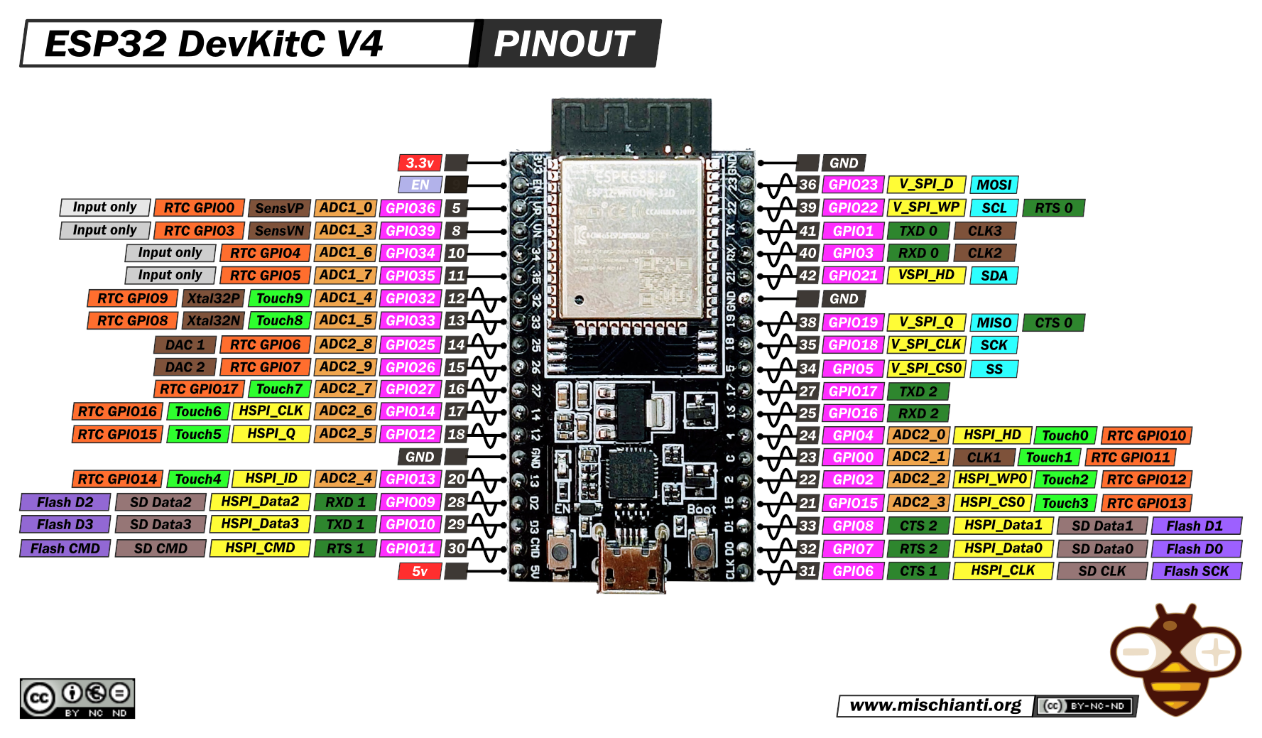
| Pin | Signal | Name | Comment |
|---|---|---|---|
| 19 | +5V | 5V | |
| 1 | +3.3V | 3V3 | |
| 14, 20, 26 | GND | GND | |
| 32 | TXD | GPIO4 | Send data |
| 30 | RXD | GPIO17 | Receive data |
| 31 | POL | GPIO16 | Polarity change |
| 35 | POW | GPIO15 | Power saving relay/SSR |
| 29 | AUX | GPIO5 | AUx relay/SSR |
| 5 | BT1 | GPIO34 | Button 1 |
| 6 | BT2 | GPIO35 | Button 2 |
| 7 | BT3 | GPIO32 | Button 3 |
| 8 | BT4 | GPIO33 | Button 4 |
| 27 | I2C_SCL | GPIO19 | |
| 28 | I2C_SDA | GPIO18 |

https://docs.m5stack.com/en/core/atom_lite
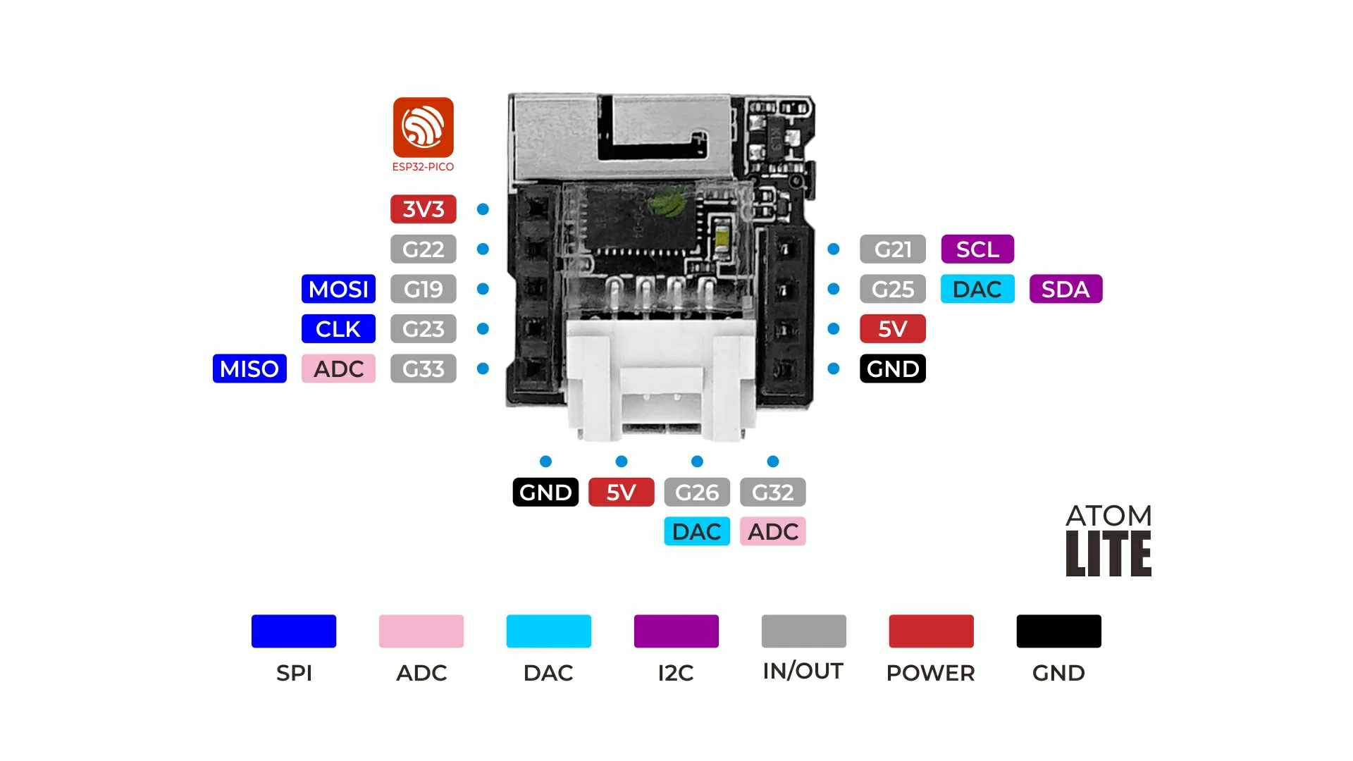
| Pin | Signal | Name | Comment |
|---|---|---|---|
| 9 | +5V | 5V | |
| 5 | +3.3V | 3V3 | |
| 10 | GND | GND | |
| 1 | TXD | G33 | Send data |
| 2 | RXD | G23 | Receive data |
| 3 | POL | G19 | Polarity change |
| 4 | POW | G22 | Power saving relay/SSR |
| 7 | I2C_SCL | G21 | |
| 8 | I2C_SDA | G25 |

| Pin | Signal | Name | Comment |
|---|---|---|---|
| 9 | +5V | 5V | |
| 8 | +3.3V | 3V3 | |
| 10 | GND | GND | |
| 3 | TXD | D0 | Send data |
| 4 | RXD | D5 | Receive data |
| 5 | POL | D6 | Polarity change |
| 6 | POW | D7 | Power saving relay/SSR |
| 7 | AUX | D8 | Aux relay/SSR |
| 12 | BT1 | D3 | Button 1 |
| 14 | I2C_SCL | D1 | |
| 13 | I2C_SDA | D2 |
| Pin | Signal | CH340-Name | Comment |
|---|---|---|---|
| 1 | GND | GND | |
| 2 | TXD | TXD | Send data |
| 3 | RXD | RXD+CTS | Receive data |
| 4 | POL | RTS | Polarity change |
| 5 | POW | nc | Power saving relay/SSR |
| 6 | AUX | nc | Aux relay/SSR |
| 7 | nc | nc | |
| 8 | +5V | nc | 5V out |
Groove-pinout with JST 2mm
| Pin | Signal | Comment |
|---|---|---|
| 1 | GND | GND |
| 2 | +5V | 5V |
| 3 | I2C_SDA | |
| 4 | I2C_SCL |
PSK or Std 2,54
| Pin | Signal | Comment |
|---|---|---|
| 1 | Relay | Switched to GND by ULN2803 |
| 2 | +5V | +5V |
PSK or Std 2,54
| Pin | Signal | Comment |
|---|---|---|
| 1 | GND | GND |
| 2 | Button 1 | Switched to GND, pullup to 5V |
| 3 | Button 2 | Switched to GND, pullup to 5V |
| 4 | Button 3 | Switched to GND, pullup to 5V |
| 5 | Button 4 | Switched to GND, pullup to 5V |
Duo-LED (red/green) with common cathode
PSK or Std 2,54
| Pin | Signal | Comment |
|---|---|---|
| 1 | LED_R | A red |
| 2 | GND | C |
| 3 | LED_G | A green |
If you plan to use an RaspberryPi of any kind and plan not to power it up all the time, it is heavily recommended to use this option, to ensure to not mess up your SD-card, your linux-installation and last but not least your Pi.
IMPORTANT: For using this functionality, it is important, to enable the "secure power off" feature of the RaspberryPi on first startup.
First, navigate to /boot/config.txt, then insert the code-lines below in section "[all]" right at the bottom of the document:
# Shutdown-button
dtoverlay=gpio-shutdown,gpio_pin=21
PSK or Std 2,54
| Pin | Signal | Comment |
|---|---|---|
| 1 | GND | |
| 2 | OFF | switched to GND, internal pullup, use short cable |


For details of the re-engineering see Electronic_AGT
An AGT is a converter to adapt a historic teletype with current loop (TW39) to a frequency shift keying station (ED1000).
The name 'AGT' stands for German "Anschaltgerät"
The device contains of
- regulated power supply (+60V, -60V and +12V)
- converter electronic H-bridge (RX, TX)
- connector for a SES-B-card (V.21 transceiver)
- ADo8 connector for teletype current loop
- power connector (Shuko) for teletype power (no fuse, no switch)
- ADo8 cable to station
- power cable to 230V wall outlet
- housing
Simply insert the SEU-M card with a Raspberry Pi (Zero (W), 1B, 2B 3) and piTelex image into the AGT and you already have a cheap alternative to participate in the i-Telex network.
The user in front of the FS will not notice any difference whether the LO2000 is operated with i-Telex or piTelex or with the SEU-M card inserted.
The SEU-M card and the Raspberry are supplied with power via the LO2000.
A Transformer provides the power for 2 independent and isolated power supplies on the same PCB.
The +60V and -60V part has a common ground. Over the H-bridge the supply provides the 120V for the TW39 current loop. The voltage is regulated by darlington transistors and Z-diodes.
The 12V part powers the data side (TX, RX) and the SEU-B device. The voltage is regulated by a LM7812 regulator.
For powering a bigger uC (like RPi) it is recommended to use the voltage before the LM7812 regulator (20V) to prevent overheating the LM7812.
Note: The 60V and 12V parts are galvanic isolated.
IMPORTANT! The 0V-power-level is connected to earth (PE). Using an oscilloscope can damage the circuit!
- Ö-AGT (without all): 3,8W
- Ö-AGT + SEU-M + RPi1 (Ruhemodus): 7,5W
- Ö-AGT + SEU-M + RPi1 (Schreibmodus): 10,0W
- Ö-AGT + SEU-M + RPiZeroW (Ruhemodus): 6,2W
- Ö-AGT + SEU-M + RPiZeroW (Schreibmodus): 11,7W
- Ö-AGT + SEU-M + RPi2B (Ruhemodus): 6,0W
- Ö-AGT + SEU-M + RPi2B (Schreibmodus): 11,0W

If the Ö-AGT is to be expanded to include a power-saving circuit, only a solid-state relay (SSR) and a fuse are required. The control is done by the piTelex software.
| Pin | Cable Color | Name | Comment |
|---|---|---|---|
| 1 | wt | in b | connected to X2-1 |
| 2 | br | in a | connected to X2-2 |
| 3 | ye | out b | connected to ADo8 4 |
| 4 | gn | out a | connected to ADo8 1 |
| 5 | nc | ||
| 6 | 12V | 12V | |
| 7 | GND | GND |
Note: No marking for this connector on the board. Numbering is assumed
| Pin | Cable Color | SES-B Pin | SES-B Name | Comment |
|---|---|---|---|---|
| 1 | wt | 3 | b | connected to X1-1 |
| 2 | br | 2 | a | connected to X1-2 |
| 3 | gn | 4 | T0 | GND |
| 4 | ye | 9 | T+ | 12V |
| 5 | gy | 11 | T- | GND |
| 6 | rs | 12 | Dab | RX - from AGT to uC, 12V level |
| 7 | bl | 15 | Dan | TX - from uC to AGT, 12V level |
| 8 | rd | 17 | B+ | 12V |
| 9 | bk | 19 | B0 | GND |
Note: No marking for this connector on the board. Numbering is assumed
The Ö-AGT and the SES-cards uses a connector with name "DIN41617".
Ö-AGT has a 31-pin female connector. The SES-cards has an 21-pin male connector with common pin 1.
For this project a 13-pol male connection (starting at pin 9) provides all necessary signal for controlling the Ö-AGT.
| Pin | Cable Color | SEU Name | Comment |
|---|---|---|---|
| 2 | br | a | connected to ADo8-cable pin 4 |
| 3 | wt | b | connected to ADo8-cable pin 1 |
| 4 | gn | T0 | GND |
| 9 | ye | +T | 12V |
| 11 | gy | -T | GND |
| 12 | rs | Dab | AGT_RX - from AGT to uC (pullup resistor of 5.6kOhm to 12V) |
| 15 | bl | Dan | AGT_TX - from uC to AGT (pullup resistor of ?kOhm to 12V) |
| 17 | rd | +B | 12V |
| 19 | bk | B0 | GND |
Note: The original SES-B-card uses 21 of the 31 pins
Additional to the SES-B pinout internal signals are available on the 31-pin connector.
The pins above 21 are used on the SEU-M-board to provide additional signals (VDD, 5V, I2C, power relay, aus relay).
| Pin | Name | Comment |
|---|---|---|
| 24 | I2C SCL | |
| 25 | I2C SDA | |
| 26 | +5V | 5V out |
| 27 | GND | |
| 28 | VDD | 12V out |
| 29 | AUX-Relay | for extern relay/SSR connected to +5V or VDD |
| 30 | POW-Relay | for extern relay/SSR connected to +5V or VDD |
| 31 | 9...24V | Input for DC/DC converter (typical in Ö-AGT) |


Research has shown that the SEU-B cards (ED1000, Germany) as well as the SES-B cards (V.21, Austria) communicate with RS232 levels (+/-12V). Also implemented in the LO2000, LO2001, LO3000, T1000S. So it makes sense to talk directly to the teletype without going through a SEU or SES card. This was also successfully possible with a USB serial adapter.
The protocol used corresponds to that of the ED1000 standard:
- TXD High with pulses: write mode / communication
- TXD permanently low: sleep mode, engine off
- RXD permanently LOW: FS in sleep mode
- RXD High: FS wants to dial (Exact procedure see i-Telex-Wiki - ED1000)
If you are in the process of laying out a board anyway, it makes sense to provide the drivers for RS232 right away. In this way, the SEU-M card can be plugged directly into the LO2000 with an alternative configuration (telex.json) instead of a classic SEU card.
Depending on the Raspberry Pi used, the network connection is via WLAN or Ethernet.
Simply insert the SEU-M card with a Raspberry Pi (Zero (W), 1B, 2B 3) and piTelex image into the teletype and you already have a cheap alternative to participate in the i-Telex network.
The user in front of the FS will not notice any difference whether the LO2000 is operated with i-Telex or piTelex or with the SEU-M card inserted.
The SEU-M card and the Raspberry are supplied with power via the LO2000.
The LO2000 and the SEU/SES-cards uses a connector with name "DIN41617".
LO2000 has a 31-pin female connector. The SEU/SES-cards has an 21-pin male connector with common pin 1.
For this project a 13-pol male connection (starting at pin 9) provides all necessary signal for controlling the LO2000.
| Pin | SEU Name | Comment |
|---|---|---|
| 2 | a | connected to ADo8-cable pin 4, routed over filter-card |
| 3 | b | connected to ADo8-cable pin 1, routed over filter-card |
| 4 | T0 | GND |
| 7 | MP-osc | Measurement point oscillator |
| 9 | +T | +12V |
| 10 | STÜ, LÜ | Check for plug is in wall outlet, pullup to 12V |
| 11 | -T | -12V |
| 12 | Dab | AGT_RX - from teletype to SEU-B-card (RS232 level) |
| 13 | LS | nc, used by TW39-card |
| 14 | LP | nc, used by TW39-card |
| 15 | Dan | AGT_TX - from SEU-B-card to teletype (RS232 level) |
| 16 | MP-dis | Measurement point discriminator |
| 17 | +B | +12V |
| 18 | -B | nc, (-12V) |
| 19 | B0 | GND |
| 20 | 2DRE | nc, used by TW39-card |
| 22 | 0V~ | nc, 60V AC (LO2000, not part off SEU-B-card) |
| 23 | 60V~ | nc, 60V AC (LO2000, not part off SEU-B-card) |
Additional to the SEU-B pinout internal signals are available on the 31-pin connector.
The pins above 21 are used on the SEU-M-board to provide additional signals (VDD, 5V, I2C, power relay, aus relay).
| Pin | Name | Comment |
|---|---|---|
| 24 | I2C SCL | |
| 25 | I2C SDA | |
| 26 | +5V | 5V out |
| 27 | GND | |
| 28 | VDD | 12V out |
| 29 | AUX-Relay | for extern relay/SSR connected to +5V or VDD |
| 30 | POW-Relay | for extern relay/SSR connected to +5V or VDD |
| 31 | 9...24V | Input for DC/DC converter (typical in Ö-AGT) |


With the SEU-M card as a controller, the LO2000 can also be operated with 75 or 100 baud. In the LO2000, only the DIP switch (light blue) on the LP9 needs to be changed (both switches for 100Bd).
- Schematics (PDF): https://github.com/fablab-wue/piTelex.supplement/blob/master/PCB_KiCad/SEU-M_1.04/PDF/SEU-M_1.04.pdf
- Board-Layout (KiCad): https://github.com/fablab-wue/piTelex.supplement/tree/master/PCB_KiCad/SEU-M_1.04
- piTelex (Experimentel-Branch): https://github.com/fablab-wue/piTelex/tree/ExperimentalFeatures-2022-01
- Ö-AGT-Hack: https://github.com/fablab-wue/piTelex/tree/ExperimentalFeatures-2022-01
- SEU_M / Ö-AGT in i-Telex Forum (German language):
